This series start with this initial post, where we looked at an implementation of a simple turtle graphics engine inside AutoCAD, and followed on with this previous post, where we refined the engine and looked at how we could use it to generate complex fractals with relatively little code.
In this post we take a further look at fractal generation using the turtle graphic engine, with the particular focus on introducing randomness to generate more realistic, organic forms. On a side note, fractals and the use of randomness in design are two of my favourite topics, so this post is hitting a sweet spot, for me. 🙂
So where to start when generating organic forms? The simplest, "classic" example, in my view, is to generate trees. Trees lend themselves to automatic generation, as - in 2D, at least - they are a sequence of simple 2-way forks (at least the way I draw them, they are :-).
I picked up some simple Logo code from this site (yes, it does indeed say "fractals for children" in the title 🙂
if :distance < 5 [stop]
forward :distance
right 30
tree :distance-10
left 60
tree :distance-10
right 30
back :distance
This is easy to turn into C# code harnessing our TurtleEngine, with the addition of a proportional trunk/branch width (we take the width as a tenth of the length). See the Tree() function in the code listing below. The results of this procedure (which you call via the FT command) are interesting enough, if a little perfect:

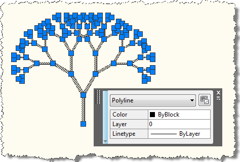
You will notice that the tree is created as a single Polyline, which is a result of us back-tracking over previous segments with the pen down, rather than up. You can see this from this image showing the tree selected:
The FT command will create the same results every single time (assuming you specify the same tree length), which may or may not be what you're after.
So let's go and add some randomness, to make life a little more interesting. This modified function in the below code, named RandomTree(), generates a separate random factor to apply to the trunk/branch length (and therefore the width, as this is proportional to the length), and to the angle of each of the two branches sprouting from the current trunk or branch. The "variability" is specified by the user for all our random factors, but we could go further and tweak it for the length and for each of the angles.
Here's the C# code, including command definitions and the TurtleEngine we refined in the last post:
using Autodesk.AutoCAD.ApplicationServices;
using Autodesk.AutoCAD.DatabaseServices;
using Autodesk.AutoCAD.EditorInput;
using Autodesk.AutoCAD.Runtime;
using Autodesk.AutoCAD.Geometry;
using Autodesk.AutoCAD.Colors;
using System;
namespace TurtleGraphics
{
// This class encapsulates pen
// information and will be
// used by our TurtleEngine
class Pen
{
// Private members
private Color m_color;
private double m_width;
private bool m_down;
// Public properties
public Color Color
{
get { return m_color; }
set { m_color = value; }
}
public double Width
{
get { return m_width; }
set { m_width = value; }
}
public bool Down
{
get { return m_down; }
set { m_down = value; }
}
// Constructor
public Pen()
{
m_color =
Color.FromColorIndex(ColorMethod.ByAci, 0);
m_width = 0.0;
m_down = false;
}
}
// The main Turtle Graphics engine
class TurtleEngine
{
// Private members
private Transaction m_trans;
private Polyline m_poly;
private Pen m_pen;
private Point3d m_position;
private Vector3d m_direction;
private bool m_updateGraphics;
// Public properties
public Point3d Position
{
get { return m_position; }
set { m_position = value; }
}
public Vector3d Direction
{
get { return m_direction; }
set { m_direction = value; }
}
// Constructor
public TurtleEngine(Transaction tr)
{
m_pen = new Pen();
m_trans = tr;
m_poly = null;
m_position = Point3d.Origin;
m_direction = new Vector3d(1.0, 0.0, 0.0);
m_updateGraphics = false;
}
// Public methods
public void Turn(double angle)
{
// Rotate our direction by the
// specified angle
Matrix3d mat =
Matrix3d.Rotation(
angle,
Vector3d.ZAxis,
Position
);
Direction =
Direction.TransformBy(mat);
}
public void Move(double distance)
{
// Move the cursor by a specified
// distance in the direction in
// which we're pointing
Point3d oldPos = Position;
Position += Direction * distance;
// If the pen is down, we draw something
if (m_pen.Down)
GenerateSegment(oldPos, Position);
}
public void PenDown()
{
m_pen.Down = true;
}
public void PenUp()
{
m_pen.Down = false;
// We'll start a new entity with the next
// use of the pen
m_poly = null;
}
public void SetPenWidth(double width)
{
m_pen.Width = width;
}
public void SetPenColor(int idx)
{
// Right now we just use an ACI,
// to make the code simpler
Color col =
Color.FromColorIndex(
ColorMethod.ByAci,
(short)idx
);
// If we have to change the color,
// we'll start a new entity
// (if the entity type we're creating
// supports per-segment colors, we
// don't need to do this)
if (col != m_pen.Color)
{
m_poly = null;
m_pen.Color = col;
}
}
// Internal helper to generate geometry
// (this could be optimised to keep the
// object we're generating open, rather
// than having to reopen it each time)
private void GenerateSegment(
Point3d oldPos, Point3d newPos)
{
Document doc =
Application.DocumentManager.MdiActiveDocument;
Database db = doc.Database;
Editor ed = doc.Editor;
Autodesk.AutoCAD.ApplicationServices.
TransactionManager tm =
doc.TransactionManager;
Plane plane;
// Create the current object, if there is none
if (m_poly == null)
{
BlockTable bt =
(BlockTable)m_trans.GetObject(
db.BlockTableId,
OpenMode.ForRead
);
BlockTableRecord ms =
(BlockTableRecord)m_trans.GetObject(
bt[BlockTableRecord.ModelSpace],
OpenMode.ForWrite
);
// Create the polyline
m_poly = new Polyline();
m_poly.Color = m_pen.Color;
// Define its plane
plane = new Plane(
m_poly.Ecs.CoordinateSystem3d.Origin,
m_poly.Ecs.CoordinateSystem3d.Zaxis
);
// Add the first vertex
m_poly.AddVertexAt(
0, oldPos.Convert2d(plane),
0.0, m_pen.Width, m_pen.Width
);
// Add the polyline to the database
ms.AppendEntity(m_poly);
m_trans.AddNewlyCreatedDBObject(m_poly, true);
}
else
{
// Calculate its plane
plane = new Plane(
m_poly.Ecs.CoordinateSystem3d.Origin,
m_poly.Ecs.CoordinateSystem3d.Zaxis
);
}
// Make sure the previous vertex has its
// width set appropriately
if (m_pen.Width > 0.0)
{
m_poly.SetStartWidthAt(
m_poly.NumberOfVertices - 1,
m_pen.Width
);
m_poly.SetEndWidthAt(
m_poly.NumberOfVertices - 1,
m_pen.Width
);
}
// Add the new vertex
m_poly.AddVertexAt(
m_poly.NumberOfVertices,
newPos.Convert2d(plane),
0.0, m_pen.Width, m_pen.Width
);
// Display the graphics, to avoid long,
// black-box operations
if (m_updateGraphics)
{
tm.QueueForGraphicsFlush();
tm.FlushGraphics();
ed.UpdateScreen();
}
}
}
public class Commands
{
static public bool GetTreeInfo(
out Point3d position,
out double treeLength
)
{
Document doc =
Application.DocumentManager.MdiActiveDocument;
Editor ed = doc.Editor;
treeLength = 0;
position = Point3d.Origin;
PromptPointOptions ppo =
new PromptPointOptions(
"\nSelect base point of tree: "
);
PromptPointResult ppr =
ed.GetPoint(ppo);
if (ppr.Status != PromptStatus.OK)
return false;
position = ppr.Value;
PromptDoubleOptions pdo =
new PromptDoubleOptions(
"\nEnter tree length <70>: "
);
pdo.AllowNone = true;
PromptDoubleResult pdr =
ed.GetDouble(pdo);
if (pdr.Status != PromptStatus.None &&
pdr.Status != PromptStatus.OK)
return false;
if (pdr.Status == PromptStatus.OK)
treeLength = pdr.Value;
else
treeLength = 70;
return true;
}
static void Tree(
TurtleEngine te,
double distance
)
{
if (distance < 5.0)
return;
// Width of the trunk/branch is a tenth of
// of the length
te.SetPenWidth(distance / 10);
// Draw the main trunk/branch
te.Move(distance);
// Draw the left-hand sub-tree
te.Turn(Math.PI / 6);
Tree(te, distance - 10);
// Draw the right-hand sub-tree
te.Turn(Math.PI / -3);
Tree(te, distance - 10);
// Turn back to the original angle
te.Turn(Math.PI / 6);
// Draw back down to the start of this sub-
// tree, with the same thickness, as this
// may have changed in deeper sub-trees
te.SetPenWidth(distance / 10);
te.Move(-distance);
}
static void RandomTree(
TurtleEngine te,
double distance,
int variability
)
{
if (distance < 5.0)
return;
// Generate 3 random factors, each on the same basis:
// a base amount = 100 - half the variability
// + a random amount from 0 to the variability
// So a variability of 20 results in 90 to 110 (0.9-1.1)
Random rnd = new Random();
int basic = 100 - (variability / 2);
int num = rnd.Next(variability);
double factor = (basic + num) / 100.0;
num = rnd.Next(variability);
double factor1 = (basic + num) / 100.0;
num = rnd.Next(variability);
double factor2 = (basic + num) / 100.0;
// Multiple out the various items by the factors
double distance1 = factor * distance;
double angle1 = factor1 * Math.PI / 6;
double angle2 = factor2 * Math.PI / -3;
// The last angle is the total angle
double angle3 = angle1 + angle2;
// Width of the trunk/branch is a tenth of
// of the length
te.SetPenWidth(distance1 / 10);
// Draw the main trunk/branch
te.Move(distance1);
// Draw the left-hand sub-tree
te.Turn(angle1);
RandomTree(te, distance - 10, variability);
// Draw the right-hand sub-tree
te.Turn(angle2);
RandomTree(te, distance - 10, variability);
// Turn back to the original angle
te.Turn(-angle3);
// Draw back down to the start of this sub-
// tree, with the same thickness, as this
// may have changed in deeper sub-trees
te.SetPenWidth(distance1 / 10);
te.Move(-distance1);
}
[CommandMethod("FT")]
static public void FractalTree()
{
Document doc =
Application.DocumentManager.MdiActiveDocument;
double treeLength;
Point3d position;
if (!GetTreeInfo(out position, out treeLength))
return;
Transaction tr =
doc.TransactionManager.StartTransaction();
using (tr)
{
TurtleEngine te = new TurtleEngine(tr);
// Draw a fractal tree
te.Position = position;
te.SetPenColor(0);
te.SetPenWidth(0);
te.Turn(Math.PI / 2);
te.PenDown();
Tree(te, treeLength);
tr.Commit();
}
}
[CommandMethod("RFT")]
static public void RandomFractalTree()
{
Document doc =
Application.DocumentManager.MdiActiveDocument;
Editor ed = doc.Editor;
double treeLength;
Point3d position;
if (!GetTreeInfo(out position, out treeLength))
return;
int variability = 20;
PromptIntegerOptions pio =
new PromptIntegerOptions(
"\nEnter variability percentage <20>: "
);
pio.AllowNone = true;
PromptIntegerResult pir =
ed.GetInteger(pio);
if (pir.Status != PromptStatus.None &&
pir.Status != PromptStatus.OK)
return;
if (pir.Status == PromptStatus.OK)
variability = pir.Value;
Transaction tr =
doc.TransactionManager.StartTransaction();
using (tr)
{
TurtleEngine te = new TurtleEngine(tr);
// Draw a random fractal tree
te.Position = position;
te.SetPenColor(0);
te.SetPenWidth(0);
te.Turn(Math.PI / 2);
te.PenDown();
RandomTree(te, treeLength, variability);
tr.Commit();
}
}
}
}
This is the first time the turtle engine has been used to apply widths to segments, so I did make a very minor change in the GenerateSegment() function: we need to apply the current pen width to the previous Polyline vertex, and not just the one we're adding. A minor change, but one that makes the engine behave in a more expected way.
When we run the RFT command, we can see a variety of trees get created - here's a quick sample:

These were created with the standard options (tree length of 70, variability of 20), but with different choices here you can get quite different results.
I hope this demonstrates the interesting capabilities turtle graphics bring to the area of modeling organic models via recursive fractals + randomness: while this was deliberately quite a simple example, this type of approach could be used/extended to generate other, more elaborate types of "natural" design in two and three dimensions.
Leave a Reply