What, yet another part? The series that just goes on and on... 🙂
To catch up, here are parts 1, 2, 3, 4 and 5, and the original post.
This post looks at more organic forms, once again, but this time in 3D. I had lots of fun with this one: I took the principle shown in Part 2, where we looked at adding random factors to fractal patterns when creating 2D trees and extended it to work with the 3D version of the TurtleEngine. The principle is the same, we're just creating three branches at relatively evenly spaced angles from each trunk (or senior branch). To add a little colour we draw "leaves" at the end (really just green cylinders, but they look good enough from a distance :-).
Here's the C# code:
using Autodesk.AutoCAD.ApplicationServices;
using Autodesk.AutoCAD.DatabaseServices;
using Autodesk.AutoCAD.EditorInput;
using Autodesk.AutoCAD.Runtime;
using Autodesk.AutoCAD.Geometry;
using Autodesk.AutoCAD.Colors;
using System;
namespace TurtleGraphics
{
// This class encapsulates pen
// information and will be
// used by our TurtleEngine
class Pen
{
// Private members
private Color m_color;
private double m_width;
private bool m_down;
// Public properties
public Color Color
{
get { return m_color; }
set { m_color = value; }
}
public double Width
{
get { return m_width; }
set { m_width = value; }
}
public bool Down
{
get { return m_down; }
set { m_down = value; }
}
// Constructor
public Pen()
{
m_color =
Color.FromColorIndex(ColorMethod.ByAci, 0);
m_width = 0.0;
m_down = false;
}
}
// The main Turtle Graphics engine
class TurtleEngine : IDisposable
{
// Private members
private Transaction m_trans;
private Polyline3d m_poly;
private Circle m_profile;
private Pen m_pen;
private CoordinateSystem3d m_ecs;
private bool m_updateGraphics;
// Public properties
public Point3d Position
{
get { return m_ecs.Origin; }
set {
m_ecs =
new CoordinateSystem3d(
value,
m_ecs.Xaxis,
m_ecs.Yaxis
);
}
}
public Vector3d Direction
{
get { return m_ecs.Xaxis; }
}
// Constructor
public TurtleEngine(Transaction tr)
{
m_pen = new Pen();
m_trans = tr;
m_poly = null;
m_profile = null;
m_ecs =
new CoordinateSystem3d(
Point3d.Origin,
Vector3d.XAxis,
Vector3d.YAxis
);
m_updateGraphics = false;
}
public void Dispose()
{
TerminateCurrentSection();
}
// Public methods
public void Turn(double angle)
{
// Rotate our direction by the
// specified angle
Matrix3d mat =
Matrix3d.Rotation(
angle,
m_ecs.Zaxis,
Position
);
m_ecs =
new CoordinateSystem3d(
m_ecs.Origin,
m_ecs.Xaxis.TransformBy(mat),
m_ecs.Yaxis.TransformBy(mat)
);
}
public void Pitch(double angle)
{
// Pitch in our direction by the
// specified angle
Matrix3d mat =
Matrix3d.Rotation(
angle,
m_ecs.Yaxis,
m_ecs.Origin
);
m_ecs =
new CoordinateSystem3d(
m_ecs.Origin,
m_ecs.Xaxis.TransformBy(mat),
m_ecs.Yaxis
);
}
public void Roll(double angle)
{
// Roll along our direction by the
// specified angle
Matrix3d mat =
Matrix3d.Rotation(
angle,
m_ecs.Xaxis,
m_ecs.Origin
);
m_ecs =
new CoordinateSystem3d(
m_ecs.Origin,
m_ecs.Xaxis,
m_ecs.Yaxis.TransformBy(mat)
);
}
public void Move(double distance)
{
// Move the cursor by a specified
// distance in the direction in
// which we're pointing
Point3d oldPos = m_ecs.Origin;
Point3d newPos = oldPos + m_ecs.Xaxis * distance;
m_ecs =
new CoordinateSystem3d(
newPos,
m_ecs.Xaxis,
m_ecs.Yaxis
);
// If the pen is down, we draw something
if (m_pen.Down)
GenerateSegment(oldPos, newPos);
}
public void PenDown()
{
m_pen.Down = true;
}
public void PenUp()
{
m_pen.Down = false;
// We'll start a new entity with the next
// use of the pen
TerminateCurrentSection();
}
public void SetPenWidth(double width)
{
m_pen.Width = width;
TerminateCurrentSection();
}
public void SetPenColor(int idx)
{
// Right now we just use an ACI,
// to make the code simpler
Color col =
Color.FromColorIndex(
ColorMethod.ByAci,
(short)idx
);
// If we have to change the color,
// we'll start a new entity
// (if the entity type we're creating
// supports per-segment colors, we
// don't need to do this)
if (col != m_pen.Color)
{
TerminateCurrentSection();
m_pen.Color = col;
}
}
// Internal helper to generate geometry
private void GenerateSegment(
Point3d oldPos, Point3d newPos)
{
Document doc =
Application.DocumentManager.MdiActiveDocument;
Database db = doc.Database;
Editor ed = doc.Editor;
Autodesk.AutoCAD.ApplicationServices.
TransactionManager tm =
doc.TransactionManager;
// Create the current object, if there is none
if (m_poly == null)
{
BlockTable bt =
(BlockTable)m_trans.GetObject(
db.BlockTableId,
OpenMode.ForRead
);
BlockTableRecord ms =
(BlockTableRecord)m_trans.GetObject(
bt[BlockTableRecord.ModelSpace],
OpenMode.ForWrite
);
// Create the polyline
m_poly = new Polyline3d();
m_poly.Color = m_pen.Color;
// Add the polyline to the database
ms.AppendEntity(m_poly);
m_trans.AddNewlyCreatedDBObject(m_poly, true);
// Add the first vertex
PolylineVertex3d vert =
new PolylineVertex3d(oldPos);
m_poly.AppendVertex(vert);
m_trans.AddNewlyCreatedDBObject(vert, true);
m_profile =
new Circle(oldPos, Direction, m_pen.Width);
ms.AppendEntity(m_profile);
m_trans.AddNewlyCreatedDBObject(m_profile, true);
m_profile.DowngradeOpen();
}
// Add the new vertex
PolylineVertex3d vert2 =
new PolylineVertex3d(newPos);
m_poly.AppendVertex(vert2);
m_trans.AddNewlyCreatedDBObject(vert2, true);
// Display the graphics, to avoid long,
// black-box operations
if (m_updateGraphics)
{
tm.QueueForGraphicsFlush();
tm.FlushGraphics();
ed.UpdateScreen();
}
}
// Internal helper to generate 3D geometry
private void TerminateCurrentSection()
{
if (m_profile != null && m_poly != null)
{
Document doc =
Application.DocumentManager.MdiActiveDocument;
Database db = doc.Database;
Editor ed = doc.Editor;
try
{
// Generate a Region from our circular profile
DBObjectCollection col =
new DBObjectCollection();
col.Add(m_profile);
DBObjectCollection res =
Region.CreateFromCurves(col);
Region reg =
res[0] as Region;
if (reg != null)
{
BlockTable bt =
(BlockTable)m_trans.GetObject(
db.BlockTableId,
OpenMode.ForRead
);
BlockTableRecord ms =
(BlockTableRecord)m_trans.GetObject(
bt[BlockTableRecord.ModelSpace],
OpenMode.ForWrite
);
// Extrude our Region along the Polyline3d path
Solid3d sol = new Solid3d();
sol.ExtrudeAlongPath(reg, m_poly, 0.0);
sol.Color = m_pen.Color;
// Add the generated Solid3d to the database
ms.AppendEntity(sol);
m_trans.AddNewlyCreatedDBObject(sol, true);
// Get rid of the Region, profile and path
reg.Dispose();
m_profile.UpgradeOpen();
m_profile.Erase();
m_poly.Erase();
}
}
catch (System.Exception ex)
{
ed.WriteMessage(
"\nException: {0}",
ex.Message
);
}
}
m_profile = null;
m_poly = null;
}
}
public class Commands
{
static public bool GetTreeInfo(
out Point3d position,
out double treeLength,
out int variability
)
{
Document doc =
Application.DocumentManager.MdiActiveDocument;
Editor ed = doc.Editor;
treeLength = 0;
position = Point3d.Origin;
variability = 0;
PromptPointOptions ppo =
new PromptPointOptions(
"\nSelect base point of tree: "
);
PromptPointResult ppr =
ed.GetPoint(ppo);
if (ppr.Status != PromptStatus.OK)
return false;
position = ppr.Value;
PromptDoubleOptions pdo =
new PromptDoubleOptions(
"\nEnter tree length <100>: "
);
pdo.AllowNone = true;
PromptDoubleResult pdr =
ed.GetDouble(pdo);
if (pdr.Status != PromptStatus.None &&
pdr.Status != PromptStatus.OK)
return false;
if (pdr.Status == PromptStatus.OK)
treeLength = pdr.Value;
else
treeLength = 100;
PromptIntegerOptions pio =
new PromptIntegerOptions(
"\nEnter variability percentage <20>: "
);
pio.AllowNone = true;
PromptIntegerResult pir =
ed.GetInteger(pio);
if (pir.Status != PromptStatus.None &&
pir.Status != PromptStatus.OK)
return false;
if (pir.Status == PromptStatus.OK)
variability = pir.Value;
else
variability = 20;
return true;
}
static void Random3DTree(
TurtleEngine te,
double distance,
int variability
)
{
// Some constants
const double kLeafSize = 3.0;
const double kBasePitch = Math.PI / 4;
const double kBaseRoll = 2 * Math.PI / 3;
const double kBranchFactor = 0.6;
const double kBranchWidth = 0.05;
const int kWoodColor = 24;
const int kLeafColor = 3;
// Under a certain size, we draw a leaf
if (distance < kLeafSize)
{
// Draw a leaf-like cylinder
te.SetPenColor(kLeafColor);
te.PenDown();
te.Move(kLeafSize);
te.PenUp();
te.Move(-kLeafSize);
return;
}
// Generate 7 random factors, each on the same basis:
// a base amount = 100 - half the variability
// + a random amount from 0 to the variability
// So a variability of 20 results in 90 to 110 (0.9-1.1)
Random rnd = new Random();
int basic = 100 - (variability / 2);
int num = rnd.Next(variability);
double factor1 = (basic + num) / 100.0;
num = rnd.Next(variability);
double factor2 = (basic + num) / 100.0;
num = rnd.Next(variability);
double factor3 = (basic + num) / 100.0;
num = rnd.Next(variability);
double factor4 = (basic + num) / 100.0;
num = rnd.Next(variability);
double factor5 = (basic + num) / 100.0;
num = rnd.Next(variability);
double factor6 = (basic + num) / 100.0;
num = rnd.Next(variability);
double factor7 = (basic + num) / 100.0;
// Multiple out the various items by the factors
double move1 = factor1 * distance;
double pitch1 = factor2 * kBasePitch;
double pitch2 = factor3 * kBasePitch;
double pitch3 = factor4 * kBasePitch;
double roll1 = factor5 * 2 * Math.PI;
double roll2 = roll1 + (factor6 * kBaseRoll);
double roll3 = roll1 + roll2 + (factor7 * kBaseRoll);
// Width of the trunk/branch is a tenth of
// of the length
te.SetPenWidth(move1 * kBranchWidth);
te.SetPenColor(kWoodColor);
te.PenDown();
// Draw the main trunk/branch
te.Move(move1);
// Draw the first sub-tree
te.Roll(roll1);
te.Pitch(pitch1);
Random3DTree(te, distance * kBranchFactor, variability);
te.Pitch(-pitch1);
te.Roll(-roll1);
// Draw the second sub-tree
te.Roll(roll2);
te.Pitch(pitch2);
Random3DTree(te, distance * kBranchFactor, variability);
te.Pitch(-pitch2);
te.Roll(-roll2);
// Draw the third sub-tree
te.Roll(roll3);
te.Pitch(pitch3);
Random3DTree(te, distance * kBranchFactor, variability);
te.Pitch(-pitch3);
te.Roll(-roll3);
// Draw back down to the start of this sub-
// tree, with the same thickness, as this
// may have changed in deeper sub-trees
te.PenUp();
te.Move(-move1);
}
[CommandMethod("3DT")]
static public void ThreeDimensionalTree()
{
Document doc =
Application.DocumentManager.MdiActiveDocument;
Editor ed = doc.Editor;
double treeLength;
Point3d position;
int variability;
if (!GetTreeInfo(
out position,
out treeLength,
out variability
)
)
return;
Transaction tr =
doc.TransactionManager.StartTransaction();
using (tr)
{
TurtleEngine te = new TurtleEngine(tr);
using (te)
{
// Draw a random fractal tree
te.Position = position;
te.Pitch(Math.PI / -2);
Random3DTree(te, treeLength, variability);
}
tr.Commit();
}
}
}
}
Bear in mind that the trees created are, once again, pretty heavy models given the level of detail. You wouldn't draw trees this way in a real-world model, for instance - it would add significant bloat to your designs.
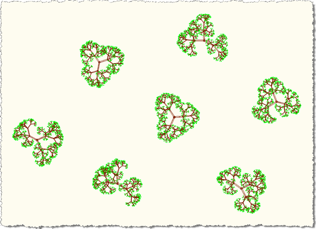
Now for some trees created by the 3DT command, taking the default options.
First in plan view:
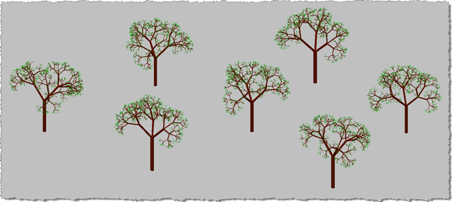
Then in full 3D:
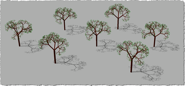
We can also use AutoCAD's sun implementation to see our trees' shadows (in this case at around 2:30pm in California):
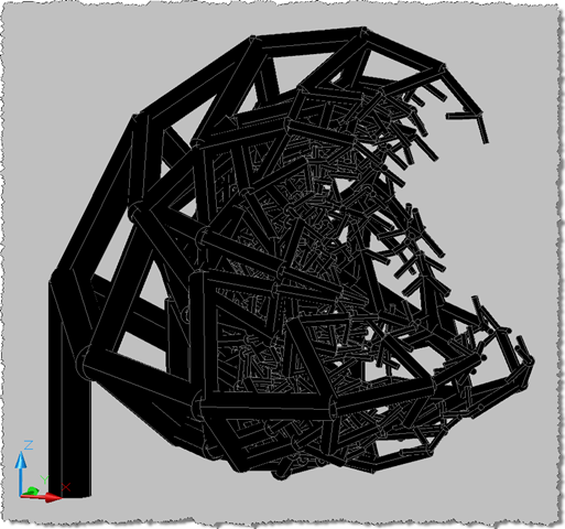
Getting the trees to draw properly was quite a challenge. Along the way there were some very interesting (even beautiful) failures... Here are a couple, for fun:
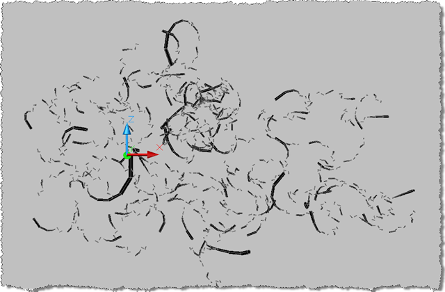
I especially liked this one:
Leave a Reply to Kean Walmsley Cancel reply