Jigs
-
Or otherwise named "Creating an AutoCAD jig to dynamically display a guilloché pattern using F#". But then why pass up the chance for a Jerry Maguire reference? 🙂 Anyway, to continue on from last week's post, Doug – who had presented the original challenge – went on to suggest that I give it the same treatment as Spiro. Basically to implement a jig to display the guilloche pattern dynamically as you input the various options. I understand the difficulty in understanding the nature of the geometry being created in the previous version… the fact that I'd named the original variables…
-
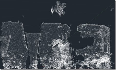
OK, here goes: my first (public) attempt at integrating the brand new Kinect Fusion functionality – made available this week in v1.7 of Microsoft's Kinect for Windows SDK – into AutoCAD. There are still a few quirks, so I dare say I'll be posting an update in due course. As mentioned in the last post, I've been working on this for some time but can now show it publicly, as the required SDK capabilities have now been published. As part of this effort, I've gone ahead and made sure the other Kinect samples I've written for AutoCAD work with this…
-
After creating a frustum-shaped jig "manually", refactoring the code while introducing the idea of an "Entity Jig Framework and then updating the framework and providing a number of usage examples, today's post looks at a slightly more complex use-case: defining a jig to create a square (in X & Y) box by selecting opposing corners. It may sound simple, but it was actually harder that it sounds – especially when supporting the use of an arbitrary User Coordinate System. It also makes use of a "phase" type that we previously hadn't needed, as we require point input for our second…
-

In the last post I introduced a simple framework to make the definition of multi-input entity jigs more straightforward. A big thanks to Chuck Wilbur, who provided some feedback that has resulted in a nicer base implementation, which we'll take for a spin in today's post. Here's the updated C# framework code that makes use of a simple class hierarchy for our phase definitions: using Autodesk.AutoCAD.DatabaseServices; using Autodesk.AutoCAD.EditorInput; using Autodesk.AutoCAD.Geometry; using System.Collections.Generic; using System; namespace JigFrameworks { // Two abstract base classes: one for all phases... public abstract class Phase { // Our member…
-
In the last post we saw some code to create a frustum-shaped Solid3d object inside AutoCAD. I mentioned at the bottom of that post that there seemed to be an opportunity to write a framework of some kind to abstract away some of the repetitive code needed to create a multi-input jig. I probably didn't say it in quite that way, but that was what I was getting at. 🙂 Anyway, after having looked at it some more, here's what I came up with: the EntityJigFramework. It's a class derived from EntityJig that encapsulates some of the common code you'd…
-
After the first three parts of this series covered the basic jig that makes use of the standard keywords mechanism to adjust text's style and rotation as it's being placed, it eventually made sense to implement the remaining requirement initially provided for the jig: this post looks at different approaches for having the jig respond to single keystrokes rather than full keyword inputs. Dave Osborne very helpfully got me started on this by providing an initial implementation that makes use of an IMessageFilter – something he'd apparently gleaned from this previous post. Thanks, Dave! 🙂 All the approaches I'll outline…
-
Earlier in this series, we implemented a jig to rotate, size and place text more easily in an AutoCAD drawing, which we then extended to allow adjustment of font-level properties. In this post, we're going to add some additional functionality to allow the text to be justified differently around the cursor location. It has to be said that the code introduced in this post isn't very extensive, but nonetheless tricky to get right (and therefore deserving of its own post). It's also worth noting that the changes would be much more complicated if we hadn't designed the code to add…
-
In the last post, we saw a simple jig implementation to position, size and rotate standard AutoCAD text. In this post, we're extending that implementation to handle font properties such as bold and italic text. At first blush, this sounds pretty straightforward – how hard can it be, right? The complexity gets introduced when we consider that these are not properties that are exposed directly from the text itself, but from the associated text style (or – to be more accurate – from the font descriptor object associated with the text style). Which begs the question: when the user chooses…
-
Back in March, I received an email from Thomas Fitou suggesting an interesting blog topic: I was thinking about a cool feature in jigs: You invoke a command to enter an Mtext or text The editor is asking for some text You enter the text Then a jig is dragged asking for position But in the editor appear some options:[R]egular [B]old [I]talic [R]otate 90 If the user hits "B" the text becomes bold If the user hits "R" the text is rotated 90 degrees If the user hits "R" again, another 90 degrees and so on... It struck me as…
-

After discovering, earlier in the week, that version 1.5 of the Kinect SDK provides the capability to get a 3D mesh of a tracked face, I couldn't resist seeing how to bring that into AutoCAD (both inside a jig and as database-resident geometry). I started by checking out the pretty-cool FaceTracking3D sample, which gives you a feel for how Kinect tracks faces, super-imposing an exaggerated, textured mesh on top of your usual face in a WPF dialog: I decided to go for a more minimalist (which also happens to mean it's simpler and with less scary results 🙂 approach for…