Graphics system
-

Everyone who uses AutoCAD – even if they use it exclusively in one or the other mode – knows that it's capable of being used to generate both 2D drawings and 3D models. Not everyone realises there are actually two distinct graphics systems in the product, however. (At least at the time of writing, talking about AutoCAD 2013… I'm not making predictions, for people reading this from the future. 🙂 The 2D graphics system is known as WHIP and has been around – albeit with regular enhancements – since the days of R13. You know if you're using WHIP if…
-
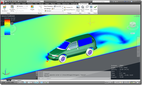
I've been waiting for this one to be published, as I've been working very closely with the team that has been developing this particular integration: Project Falcon for AutoCAD is now available on Autodesk Labs. The integration is really impressive: they've managed to really push the limits of the AutoCAD transient graphics API with some pretty incredible results. They've used a number of techniques that have also been shared on this blog to get the application working. It's hard to do it justice with pictures – download it for 64-bit AutoCAD and take it for a spin! Now if I…
-
I've taken a few days off to visit some very old friends who are back in the UK from New Zealand for the festive season, but thought I'd go ahead and share some code I've been playing with, even if I can't actually tell you what it's for. I can tell you what it does, of course, but I'm using it in conjunction with some other capabilities that I'm probably not allowed to talk about explicitly. Feel free to speculate at your leisure, I may or may not be able to confirm or deny your suspicions (I need to check…
-
After creating a frustum-shaped jig "manually", refactoring the code while introducing the idea of an "Entity Jig Framework and then updating the framework and providing a number of usage examples, today's post looks at a slightly more complex use-case: defining a jig to create a square (in X & Y) box by selecting opposing corners. It may sound simple, but it was actually harder that it sounds – especially when supporting the use of an arbitrary User Coordinate System. It also makes use of a "phase" type that we previously hadn't needed, as we require point input for our second…
-

In the last post I introduced a simple framework to make the definition of multi-input entity jigs more straightforward. A big thanks to Chuck Wilbur, who provided some feedback that has resulted in a nicer base implementation, which we'll take for a spin in today's post. Here's the updated C# framework code that makes use of a simple class hierarchy for our phase definitions: using Autodesk.AutoCAD.DatabaseServices; using Autodesk.AutoCAD.EditorInput; using Autodesk.AutoCAD.Geometry; using System.Collections.Generic; using System; namespace JigFrameworks { // Two abstract base classes: one for all phases... public abstract class Phase { // Our member…
-
In the last post we saw some code to create a frustum-shaped Solid3d object inside AutoCAD. I mentioned at the bottom of that post that there seemed to be an opportunity to write a framework of some kind to abstract away some of the repetitive code needed to create a multi-input jig. I probably didn't say it in quite that way, but that was what I was getting at. 🙂 Anyway, after having looked at it some more, here's what I came up with: the EntityJigFramework. It's a class derived from EntityJig that encapsulates some of the common code you'd…
-

As promised, here's the cleaned-up code to jig a frustum inside AutoCAD. When I took on the task of writing this code – live, during the "AutoCAD Programming Gurus Go Head to Head" class at AU – I thought to myself "that should be easy enough – I'm sure I have some code to jig a solid on my blog". Well, I did, but it turned out the code showed how to jig a box, and the code was in Python and Ruby but not C#. So I ended up having to code for my supper, after all. 😉 One…
-
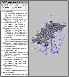
I'm really excited about this. A new programming language and environment for AutoCAD is now available for download on Autodesk Labs (and here's the announcement on Scott's blog, in case, and you should also be aware of this login/download issue – something I just ran into myself). Way back when, I helped integrate the initial incarnation of DesignScript – although at the time we were using its working name, D# – inside AutoCAD. The father of the language, Robert Aish, was put in touch with me on October 17th 2008 and by the time I headed for Las Vegas on…
-

A developer had an interesting requirement that I thought I'd spend some time looking at: to animate transient graphics inside AutoCAD according to data they've pulled in from an external simulation system. It's clear that AutoCAD is really not an animation platform – we have other products that are better suited to working in this way – but I thought it would be interesting to see what was possible. I decided to take the implementation shown in this previous post and throw in some code to animate a few different things: Change the per-vertex colours of our transient box These…
-
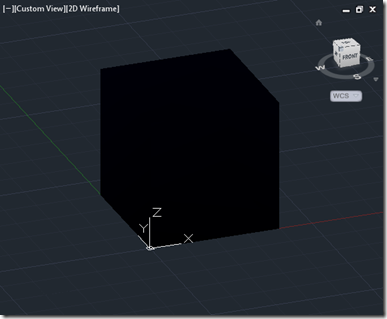
In the last post, we introduced some code to generate transient graphics using WorldGeometry.Shell(). In this post we'll make one simple addition: we'll add per-vertex colours, to see the effect on the generated box. We're not going to perform complex calculations to determine the appropriate colours for each vertex: we'll just use the index of the vertex itself, in much the same way as we did for the faces. As faces and vertices in no way match, index-wise, we should see some interesting effects. Here's the modified C# code. There is only one addition to the previous code: a call…